Line following robots are a great example of autonomous robot behaviour. In this article, I will show you step-by-step how to add a line sensor to a Raspberry Pi Pico robot, how to wire it in, and then how to write Python code for responsive line following on the robot. I include CircuitPython and MicroPython examples.
If you have a robot with motors and a Python capable microcontroller, this will be a way to add reasonably fast line following to it.
For this build, I chose the Cytron maker line. It uses 5 GPIO data pins, but is simple to interface with and has handy debug lights to show what is going on. At £8, it is also relatively cheap. It has 5 line sensors, which lets you use a pretty fast method of following. The code here will work with other 5 digital input line sensors.
Alternatives to this are to buy 5 individual line sensors. For use with an analog line/reflectance sensor or i2c/serial type, this code would need to be adapted.
What you’ll need
- A robot with motors, motor driver and a Raspberry Pi Pico (or similar CircuitPython board). The one built in Robotics at Home With Raspberry Pi Pico will work for this. You’ll need 5 free GPIO pins.
- A
robotmodule with aset_speedfunction that accepts a motor number and a speed between-1.0and1.0like the code from my book Robotics at Home With Raspberry Pi Pico. You can also adapt this for your own motor control code. - The
robotmodule should also have astopfunction that will stop all the motors. - The Cytron maker line https://thepihut.com/products/maker-line-simplifying-line-sensor
- You may need extra M3 stand offs, but note that some come with the maker line kit and may be suitable.
- A strip of 7 male to female 2.54mm DuPont leads.
- A line following test track. My book Learn Robotics Programming has a tutorial on building this.
About the Maker Line
Like many line followers, the maker line uses reflected light to detect the presence of the line. It shines an invisible beam down from each sensor, and measures the response. It has an on-board chip that you’ll calibrate to detect the line from the background, which then outputs 5 digital signals you can use in detection.
It also has an analog output, but we will not be using that in this tutorial.
Attaching the Line follower
To ensure effective line following, it’s crucial to attach the line follower correctly. Follow these steps to securely mount the line follower on your robot chassis:
-
Placement: Position the line follower close to the floor, a couple of millimetres above the ground but not touching it. Make sure it doesn’t cause any drag under the robot. This lets the sensor to detect the line effectively.
-
Stand-Off Kit: Use a stand-off kit to position the line follower below the robot. The Maker Line has slots that accommodate various bolting hole placements, offering flexibility in mounting. You can either drill holes in the robot’s chassis or use existing holes if it’s predrilled.
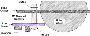
The diagram above shows how to attach it. You should plan for the lowest part of this line sensor, usually the large capacitors, to have clearance above the lowest point of the robot wheels.
-
Placement Considerations: Plan for the lowest part of the line sensor, typically the large capacitors, to have sufficient clearance above the lowest point of the robot’s wheels. This clearance ensures that the line follower doesn’t interfere with the robot’s movement
-
Secure with Standoffs: Insert the M3 standoff thread through the chassis and secure it with a nut. Repeat this on each side. You may need a combination of standoffs to get the right height. Once the standoffs are in place, use M3 bolts to fasten the line follower onto the chassis. This setup allows easy removal and adjustment of the line follower by accessing the bolts below.
By following these steps, you can ensure that the line follower is properly attached to your robot, enabling accurate line following and smooth navigation along the desired path.
Wiring
This device has the following pins:
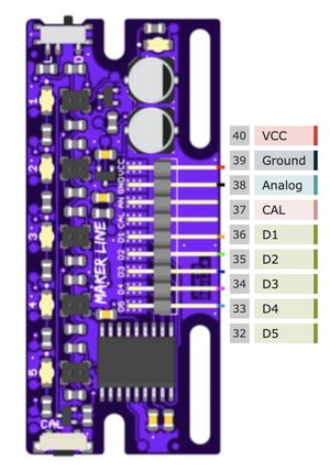
- Connect the VCC pin to the 3.3v pin on the Raspberry Pi Pico. This supplies power to the Maker Line
- Connect the GND pin to a ground pin on the Raspberry Pi Pico. This completes the power circuit for the Maker Line.
Next, you need to establish connections for line detection signals:
- Connect the D1 pin of the Maker Line to a free GPIO pin on the Raspberry Pi Pico. This will be used for line detection from the first sensor.
- Connect the D2 pin of the Maker Line to another available GPIO pin on the Raspberry Pi Pico. This will handle line detection from the second sensor.
- Continue this process for the D3, D4, and D5 pins, connecting each to separate GPIO pins on the Raspberry Pi Pico. These pins will carry the line detection signals from the remaining sensors.
Calibrating the sensor
Calibrating the Cytron Maker Line is a crucial step to ensure accurate line detection. Follow the summarised procedure below, and refer to the Maker Line Datasheet for detailed instructions:
- Power up the robot without any code running.
- Position the robot so that the line sensor is over a line.
- Adjust the switch on the Maker Line to match the test area’s conditions, whether it’s a dark line or a light line.
- Press and hold the calibrate button for 2 seconds - the LED’s will progress across, and then start blinking.
- Wave the Maker Line over the line and background a few times to allow it to adapt to the specific surface.
- Press the calibrate button again to finish calibration. The LED lights should sweep back and forth, indicating that calibration is completed.
If you encounter any difficulties during the calibration process, refer to the Maker Line Datasheet for comprehensive guidance and troubleshooting tips.
Setting up the line following pins
We start this code with some setup and imports:
import board
from digitalio import DigitalInOut, Direction
import robot
Next, we’ll configure the data input pins as Digital pins with direction in:
line_sensor = [
    DigitalInOut(board.GP10),
    DigitalInOut(board.GP11),
    DigitalInOut(board.GP12),
    DigitalInOut(board.GP13),
    DigitalInOut(board.GP14),
]

for pin in line_sensor:
    pin.direction = Direction.INPUT
Here, we configure 5 digital input pins for a single sensor array. The function get_average_line_position calculates the average position of activated sensors, indicating if the line is close to the middle of the array:
def get_average_line_position():
    outputs = []
    for n, sensor in enumerate(line_sensor):
        if sensor.value:
            outputs.append(n + 1)
    if outputs:
        return sum(outputs)/len(outputs)
    else:
        return 0
This will add a number for each sensor input that is activated, the index + 1. The index from the python enumerate would start at zero, but we want it to be 1, 2, 3 ,4 5, so we add one.
We then divide the total by the number of activated items, so the result will be the average position of activated sensors.
Optimization Note: The current implementation is relatively simple and suitable for the provided code context, considering the use of significant sleep times. If you need to optimize the code further, consider profiling and benchmarking specific use cases.
Implementing the Line Following Algorithm
To make our robot follow the line smoothly, we’ll implement a line following algorithm using Proportional Control. This algorithm will convert the sensor input into motor steering data, allowing our robot to maintain its position relative to the line. Don’t worry if you’re not familiar with Proportional Control; it’s a straightforward concept we’ll use to achieve smooth line following behaviour.
We will use Proportional Control for this activity, where we compare the average line with an expected middle to calculate an error value.
        # Calculate the error value based on the difference between the line position and expected position
        actual = get_average_line_position()
        error = LINE_MIDDLE - actual

        # Apply the Proportional Control constant to the error to get the correction value
        correction = error * PROPORTION
        print(line, error, correction)
We then multiply it by a proportion and print it out.
Before diving into the code, let’s define some constants and parameters at the beginning for easy adjustments:
LINE_MIDDLE = 3   # The middle sensor position
PROPORTION = 0.1  # Proportional Control constant (fine-tune as needed)
SPEED = 0.4       # Preset motor speed for straight movement
Back in the loop, we can take that correction, and apply it to motor speeds:
        robot.set_speed(0, SPEED + correction)
        robot.set_speed(1, SPEED - correction)
By using Proportional Control, we can ensure that the robot smoothly follows the line detected by the sensors. Feel free to adjust the constants and parameters to optimize the performance of your line following robot.
Worked examples
The diagram below shows two worked example scenarios to understand this algorithm:
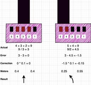
The diagram shows two scenarios. In the first scenario, the line is in the middle of the sensor. In the second scenario, it is to the left of the robot.
The actual line data is calculated with get_average_line_position . When sensors 4, 3 and 2 are covered, they sum to 9, with 3 lit sensors, this is an average of 3.
The error is based on our intended line middle position, 3. So when we compare them, we get an error of 0. This is multiplied by the proportional constant, and results in a correction of 0.
The correction is applied to the motor speeds, and results in the robot driving forward.
In the second scenario, the sensors 5 and 4 will be activated. The average of these is 4.5. Comparing this with 3 gives an error of -1.5. We multiply this by the proportional constant of 0.1, getting a correction of -0.15.
We then apply this correction by subtracting it from the nearer motor, giving a speed of 0.25 there, and adding to the other motor, giving a speed of 0.55. The robot will now turn towards the line. A positive correction will cause the robot to turn in one direction, and a negative correction the other way.
By adjusting the number of sensors and the LINE_MIDDLE constant, this algorithm will work for 5 sensors, 3 or 12!
Bringing it together
So far, you’ve seen a few fragments. We need that main loop, and some error handling to ensure the robot stops when things go wrong.
The whole file, perhaps call it line_follow.py looks like this:
import board
from digitalio import DigitalInOut, Direction
import robot

LINE_MIDDLE = 3   # The middle sensor position
PROPORTION = 0.1  # Proportional Control constant (fine-tune as needed)
SPEED = 0.4       # Preset motor speed for straight movement

line_sensor = [
    DigitalInOut(board.GP10),
    DigitalInOut(board.GP11),
    DigitalInOut(board.GP12),
    DigitalInOut(board.GP13),
    DigitalInOut(board.GP14),
]

for pin in line_sensor:
    pin.direction = Direction.INPUT

def get_average_line_position():
    outputs = []
    for n, sensor in enumerate(line_sensor):
        if sensor.value:
            outputs.append(n + 1)
    if outputs:
        return sum(outputs)/len(outputs)
    else:
        return 0

# Main line following loop
try:
    while True:
        # Calculate the error value based on the difference between the line position and expected position
        actual = get_average_line_position()
        error = LINE_MIDDLE - actual

        # Apply the Proportional Control constant to the error to get the correction value
        correction = error * PROPORTION
        print(line, error, correction)
        robot.set_speed(0, SPEED + correction)
        robot.set_speed(1, SPEED - correction)
        time.sleep(0.04)

finally:
    # Ensure the robot stops when exiting the loop
    robot.stop()
The finally block here ensures the robot stops gracefully when exiting the loop, even if there are exceptions.
You will need to upload this file, along with the robot.py file to your Pico.
You can then put import line_follow in code.py to start it, or make line_follow the content of code.py.
Micropython version
This is also easily adapted to Micropython by changing the imports and line setup. The other code remains the same.
from machine import Pin
import time
import robot

.
.
.

line_sensor = [
    Pin(10, Pin.IN),
    Pin(11, Pin.IN),
    Pin(12, Pin.IN),
    Pin(13, Pin.IN),
    Pin(14, Pin.IN)
]
Testing
I recommend you start testing with your laptop connected, to flush out bugs and tune it.
Once this is working, then you can untether it and let it go on a line on the floor. This will require the robot to be over the line, it does not really have a seek behaviour if there’s no line under the sensors.
Tuning
You may find that the robot is understeering, that is, not quite finding the line. For this, you can reduce the speed, or increase the proportion. The proportion can be a little over the speed it it’s 0.5 or less - a wheel would turn backwards so the robot will turn on the spot.
If the robot is oversteering, then you can increase the speed, or decrease the proportion.
Once you’ve used the print to debug, you can comment that out, and reduce the sleep time. Note that as there are motor response times you will hit diminishing returns there.
If you know how, you could look at adding Integral and Derivative components to this line follow, see Robotics at Home with Raspberry Pi Pico for how to do that.
Next steps
If you know other robot builders who would enjoy this, please share the article with them. Have you built a robot with line following? Send them to me on discord, linkedin or facebook, I’d love to see them. I’m also happy to talk about the algorithm and improvements to the code.
If you want to build more robot behaviours, consider buying Robotics at home with Raspberry Pi Pico.
Reference material
- My book Robotics at home with Raspberry Pi Pico has a bunch of material to help with this and building more robot projects:
- CircuitPython motor code
- Building a robot chassis
- Getting started with CircuitPython
- More information on using the PID algorithm to control robots
- For the Cytron maker line - see https://my.cytron.io/p-maker-line-simplifying-line-sensor-for-beginner
- For help with CircuitPython Digital Inputs - see https://learn.adafruit.com/circuitpython-essentials/circuitpython-digital-in-out