Tiny Toolkit Drill bit tray
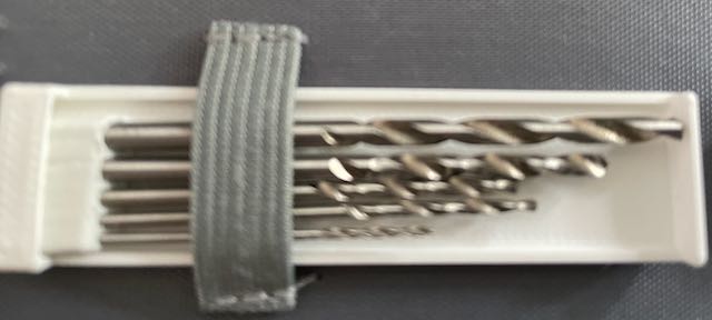
Jarkman, the person who inspired my tiny toolkit suggested making and 3D Printing a tray so the bits are less likely to escape into the toolbag. This is building on the Drill bits holder I made yesterday.
I’ve used FreeCAD to make such a thing. I started by making a drawing of the original part for dimensions, and using that to draw the second part. I’ve not reliably found a way to sketch a new part related to/constrained by a first part in FreeCAD yet - I just have to sketch another part using the output dimensions from the first to constrain it. I’m probably still getting up to speed on FreeCAD.
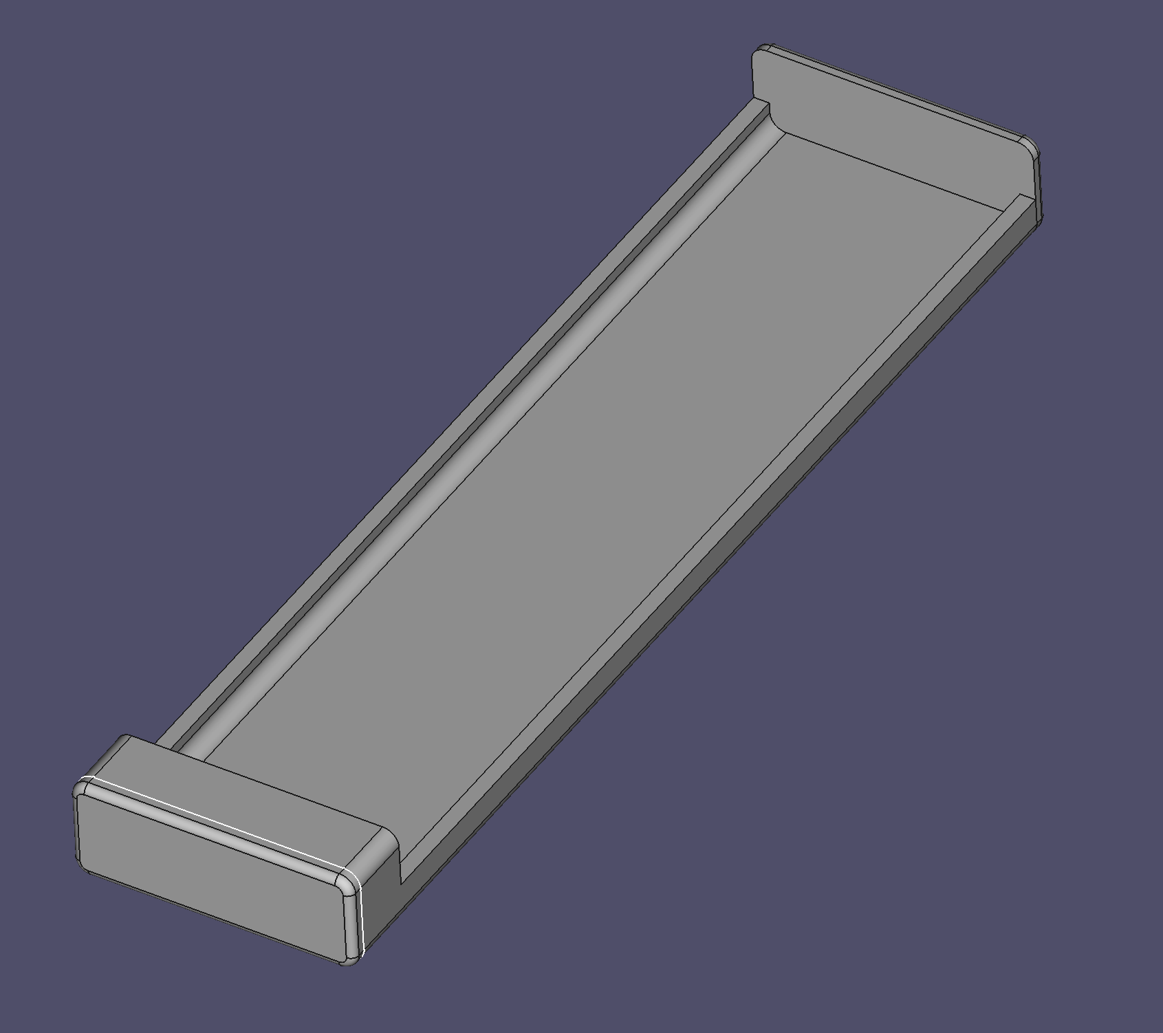
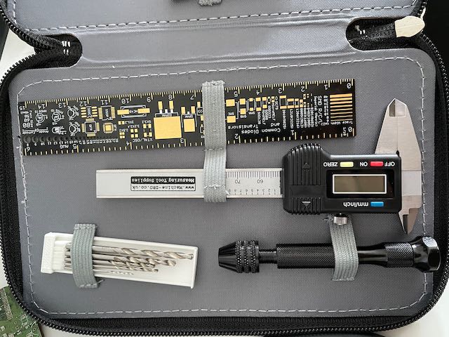
I based the vertical dimension on using the calipers (handily in the same toolkit pocket as the drills) to measure the longest one.
My observations while making this
- I had to redo this part, I tried to be cheeky and use an existing part plane, and was almost immediately struck by the FreeCAD topological naming issue when I changed something. Yeah, used a Datum plane.
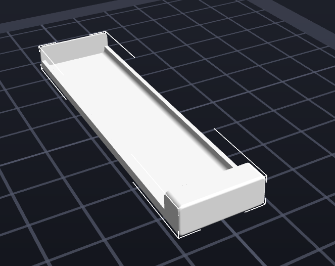
- It took me a while to figure out the top cap. I was hoping to pad the shapebinder for the outside a second time but offset, but FreeCAD doesn’t let you do this. Another plane, and tracing the sketch below was my solution. I’d still rather be able to reference the original sketch or it’s shape binder.
- I liked finding the FreeCAD rounded rectangle sketch tool, not sure how I’d missed that before.
- My FlashForge Printer always pre-extrudes, even when I say not to (the default settings in Flashforge are to).
- It printed well other than the annoying pre-extrusion I had to quickly clear.
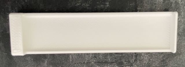
- I may have been pushing my luck with tight tolerances and the bridging needed on the front layer. I needed only a little filing finish on that overhang
- It was a 17 minute print - fairly quick really.
- Perhaps this was too simplistic, and should have drill bit separators, but it will keep things together a bit more.
A victory
I’m already using this toolkit enough to really help. When making this - having the drill handle and bits (in the loose box) meant not going over to the larger toolchests. Having the calipers handy meant this was an easy reach. I had the file in another pocket of the same toolkit - so between the 3D printer (at my desk), the laptop (at my desk) and the toolkit - I didn’t have to move around at all (I should go take a walk to exercise a bit) while making this. Definitely improving my making experience.
Last night, while doing some minor work on a Raspberry pi Pico robot (for my upcoming book), I was similarly able to use this kit to do all the part changes - some measurements, pencil markings and 4 2mm holes. I had the spanner handy, did have to reach for the tiny bolts, washers and nuts along with the small alan key needed (that is gonna go in next).
Next steps
I do need to keep a pencil and eraser in the kit - that is easy enough. I’m also thinking a tiny stock of male-female dupont cables as I’m often reaching for them.
I’m also not convinced I use all the screwdriver types often enough to justify them, plus the ones I’ve put in seem wide for the kit. Might need to think about what will work here.
I was considering putting the drill bit sizes on the front of the print, but they will be kinda tiny and I’m not sure the printer would make them that readable. Plus knowing the range and step of 0.5, it’s pretty obvious now.
I also want to indicate the front of the toolbox. Might be a place to put an orionrobots logo! 😀