Raspberry Pi Pico Wifi and Wireless
These last few months, I’ve been working on things related to an upcoming Raspberry Pi Pico robotics book. The current few weeks have been relating to using an add on Wifi solution. While I’ll go into detail in the book, there have been many difficulties in getting this to work.
The basic solution
The concept I’ve taken to is using an Adafruit AirLift as a WiFi coprocessor. This runs a WiFi stack as firmware, with CircuitPython libraries to talk to it over SPI. It is relatively compact, and is based upon the ESP32 board.
Power Issues
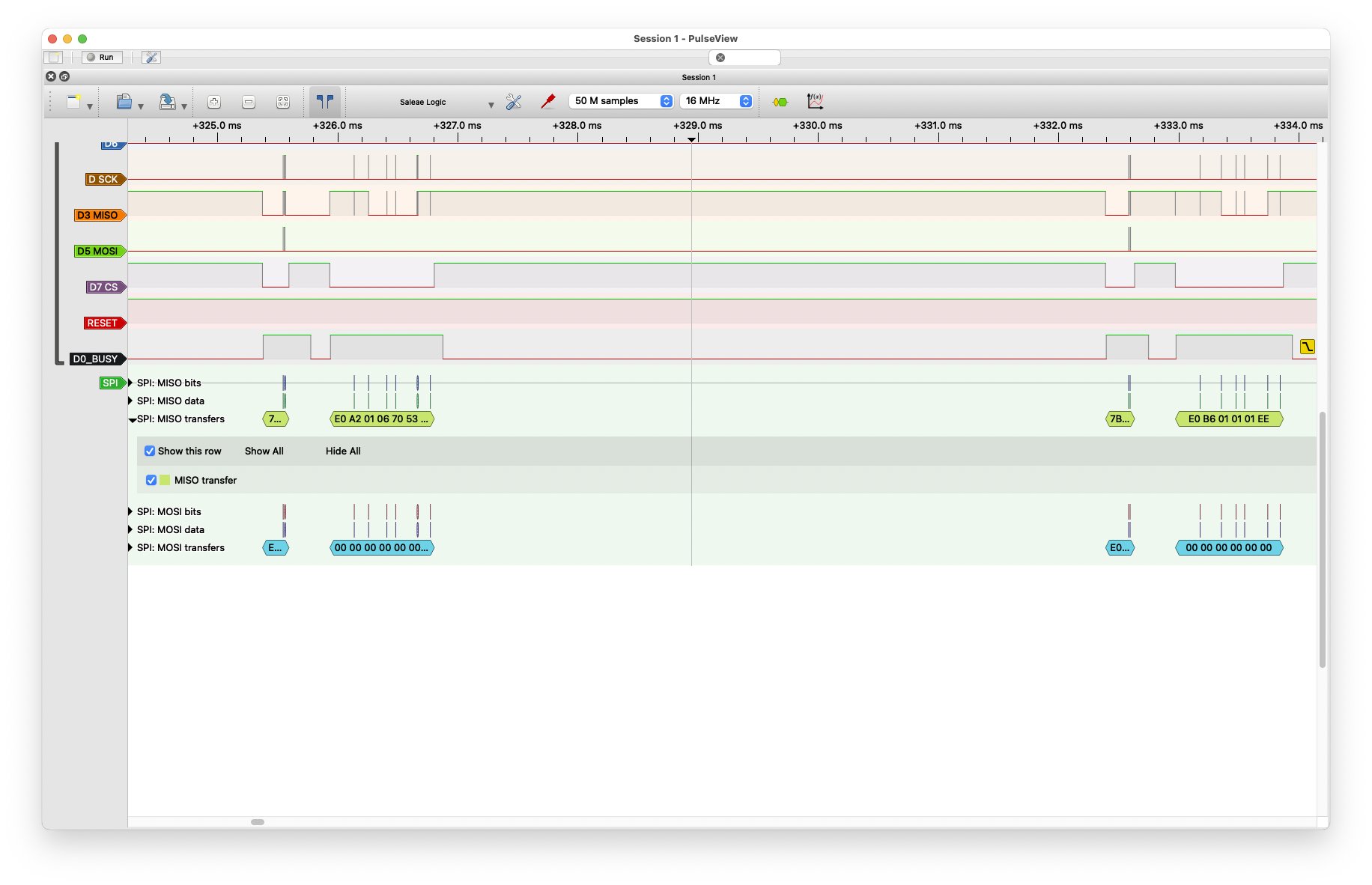
The investigation started with seeing SPI communication issues.
ESP32 timed out on SPI select
At this point, the Airlift would either not start, or would die as soon as I tried to connect it to Wifi.
I plugged it into a logic analyser to see what I could make of the SPI bus at this time.
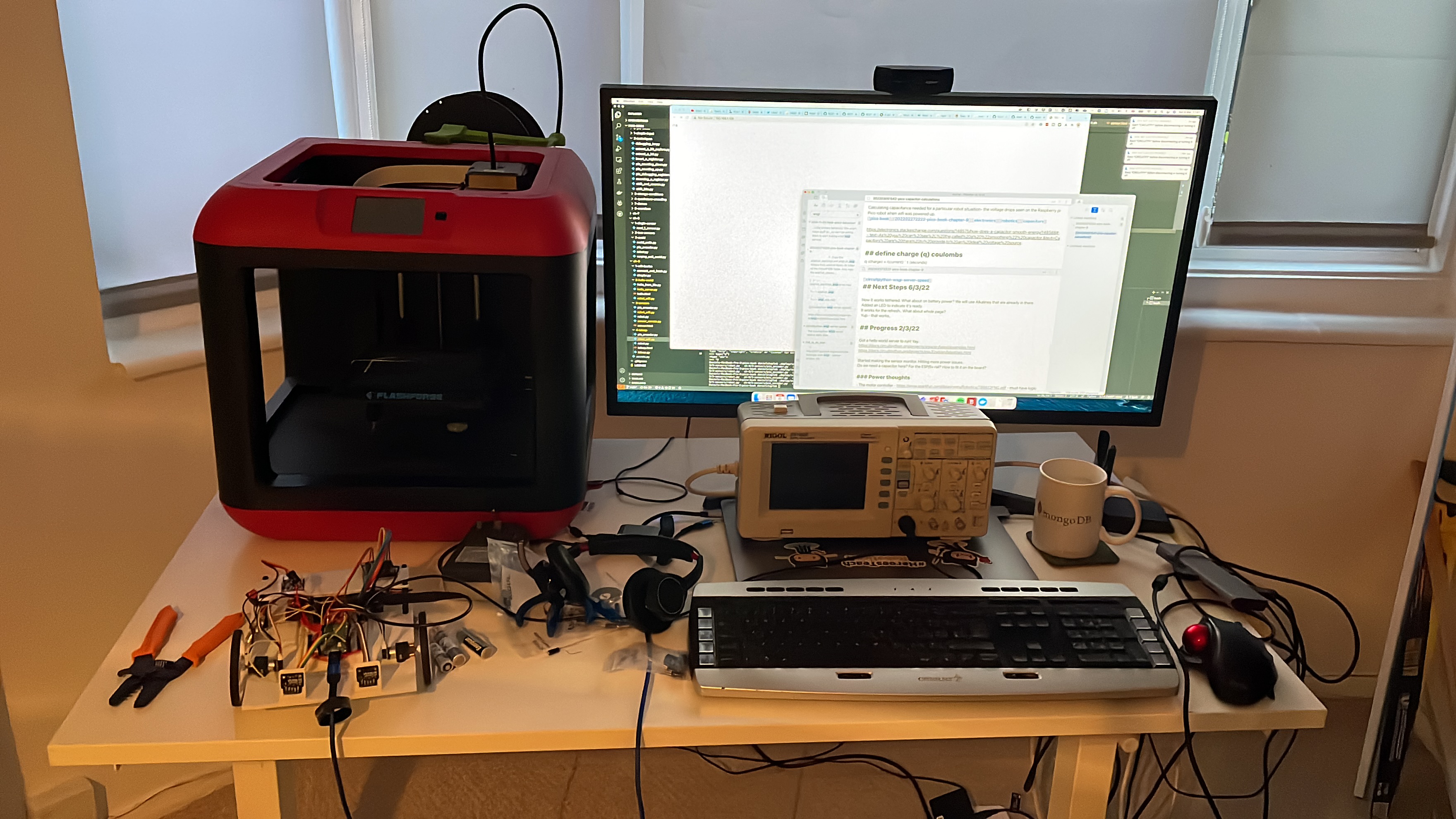
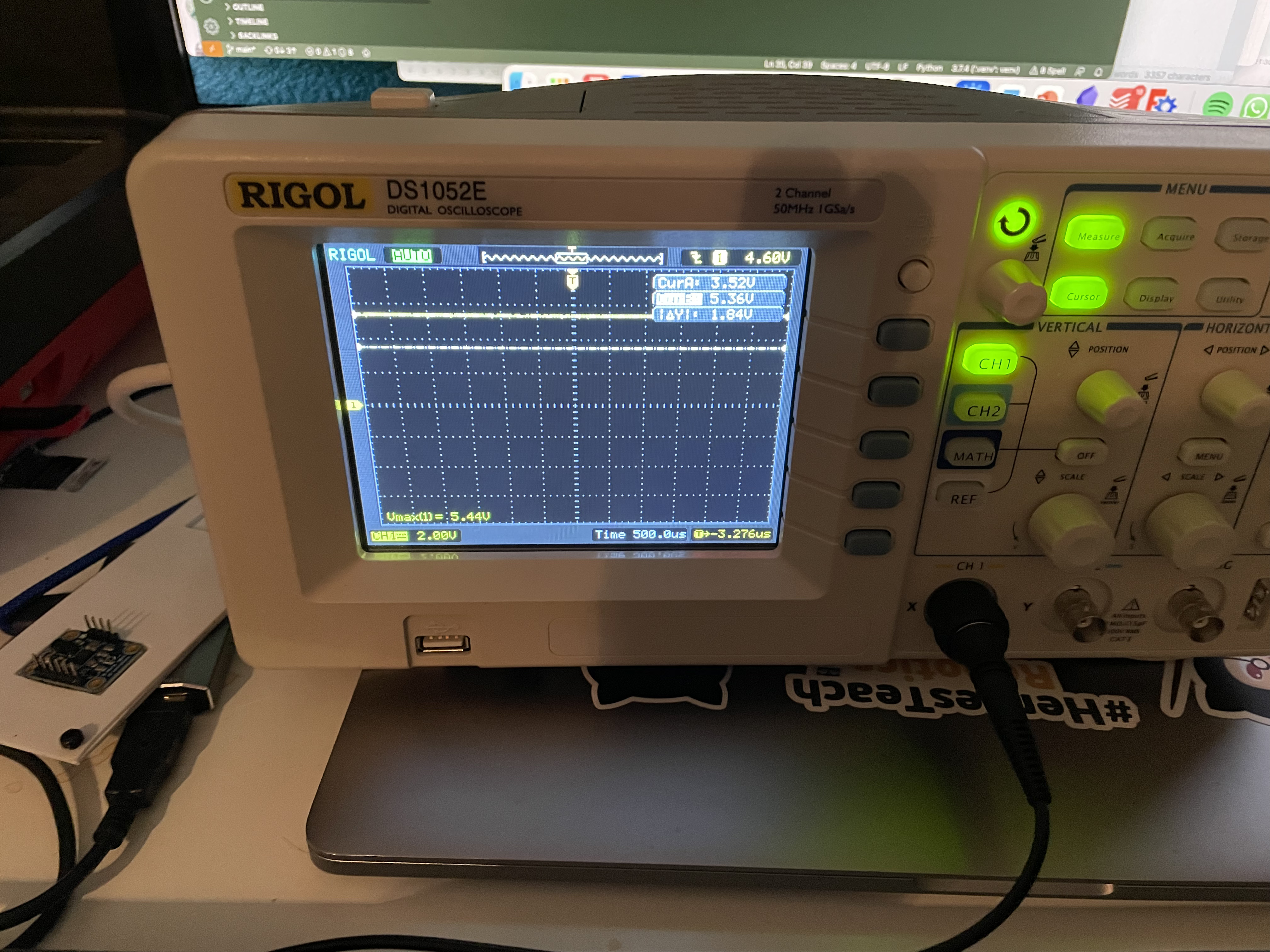
First it became clear that the Airlift requires much more power than any other logic device on the robot. I had sat with an oscilloscope watching this play out.
I’d tried putting a capacitor in parallel to cope with these power demands, but it wasn’t enough. For this, I built a power board for the robot, on a tiny red board.
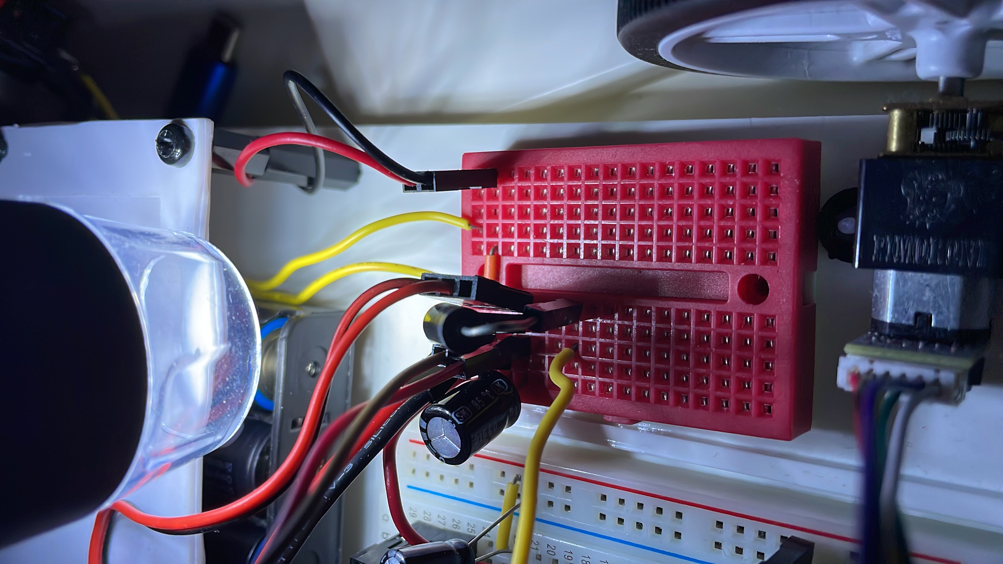
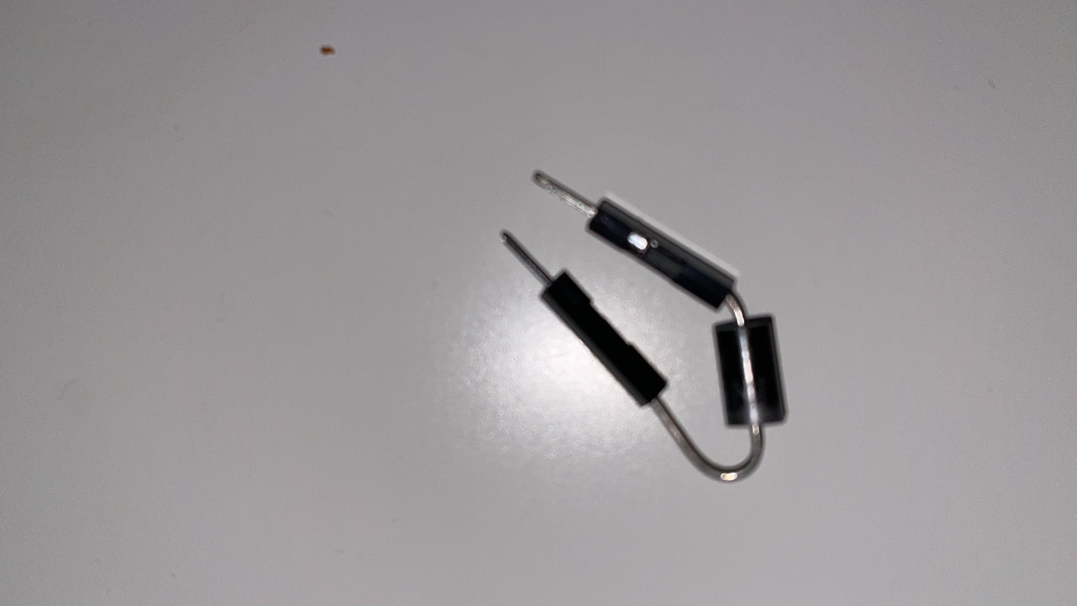
I added a diode for the VSYS power, as I’d had a few issues because I’d not read the data sheet properly and missed this requirement. This means that I could have it plugged into the PC with battery power. The diode I first tried was a Schottky - but a 3a model that was a bit too thick for the breadboard, my hack to fit it was to crimp some male terminals on the end.
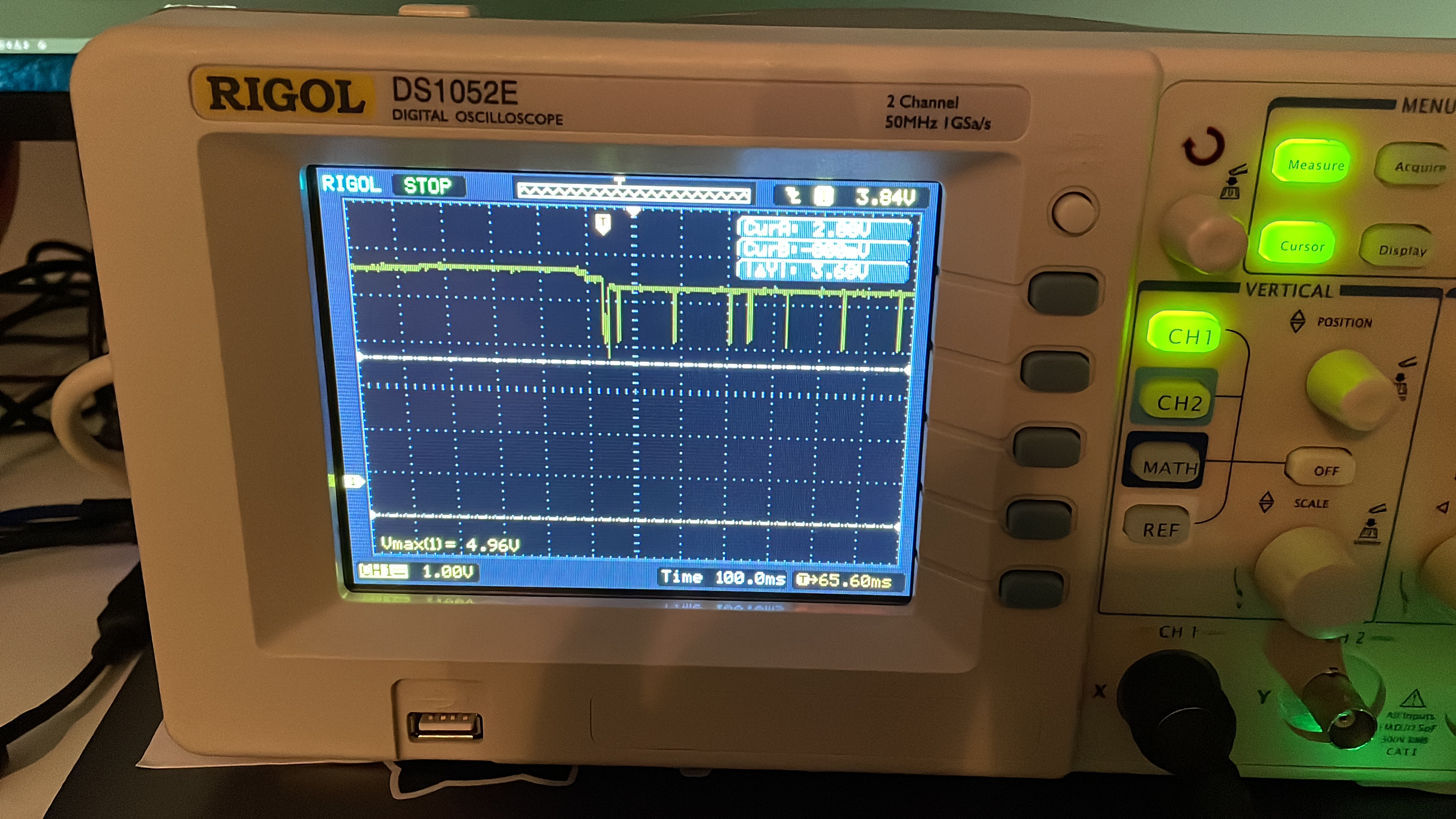
I was able to wire this into the oscilloscope probes, and see that the gulps were shortened, but still deep enough to cause issues.
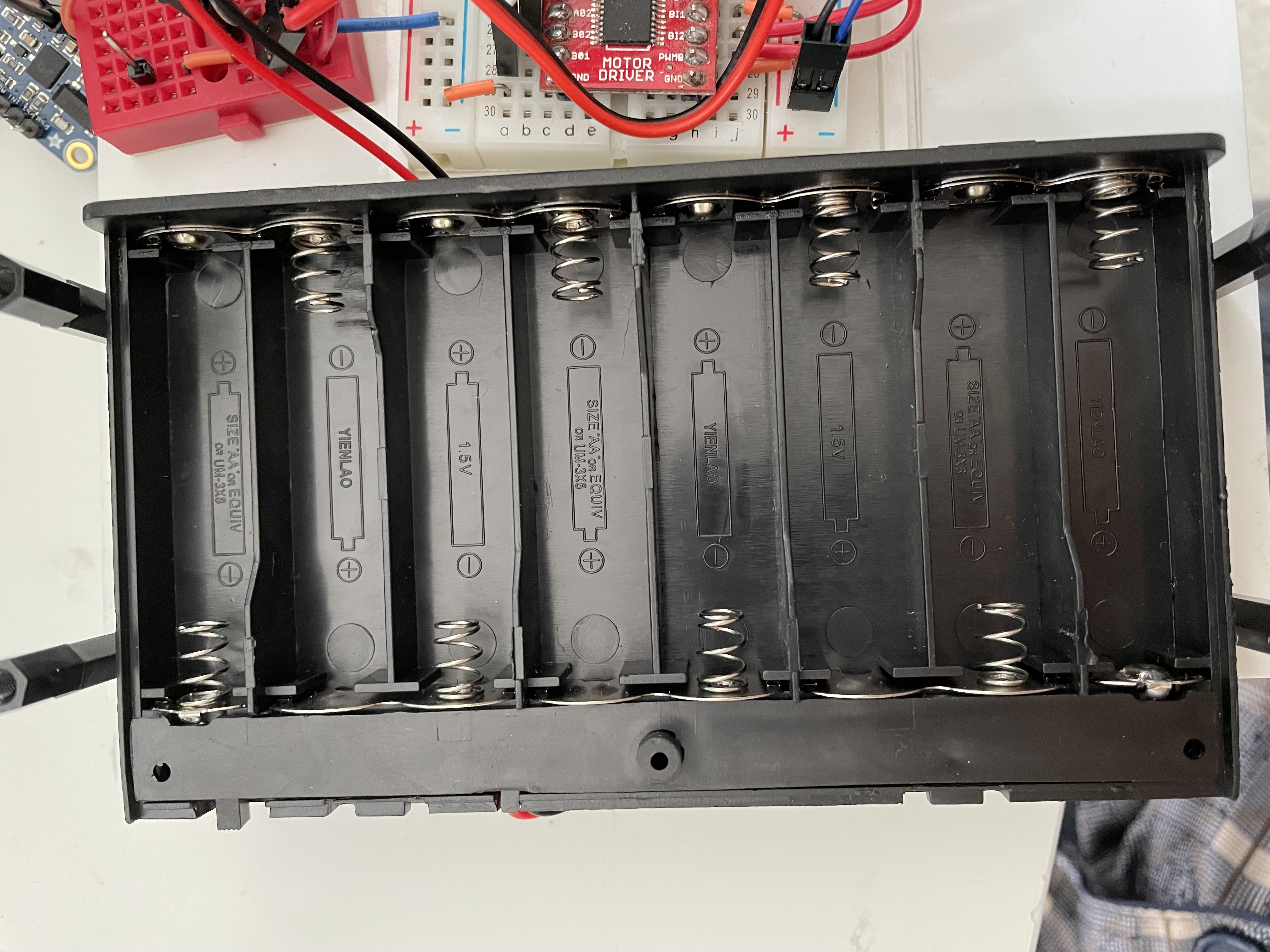
There were still huge gulps of power. Although there was a capable 5v 3A UBEC on board, I was using 6x AA batteries. What I’d determined was that 6 batteries - AA or NiMH, put me too close to the headroom needed by the UBEC for it to operate. This would be at 9v for Alkaline, but with poor current performance that Alkaline often give, and 7.2v for NiMH. With NiMH - you get 2.2v headroom. With power supplies like this, when there is a lot of current demanded, without much voltage headroom at their input, you may see voltage drops on the output.
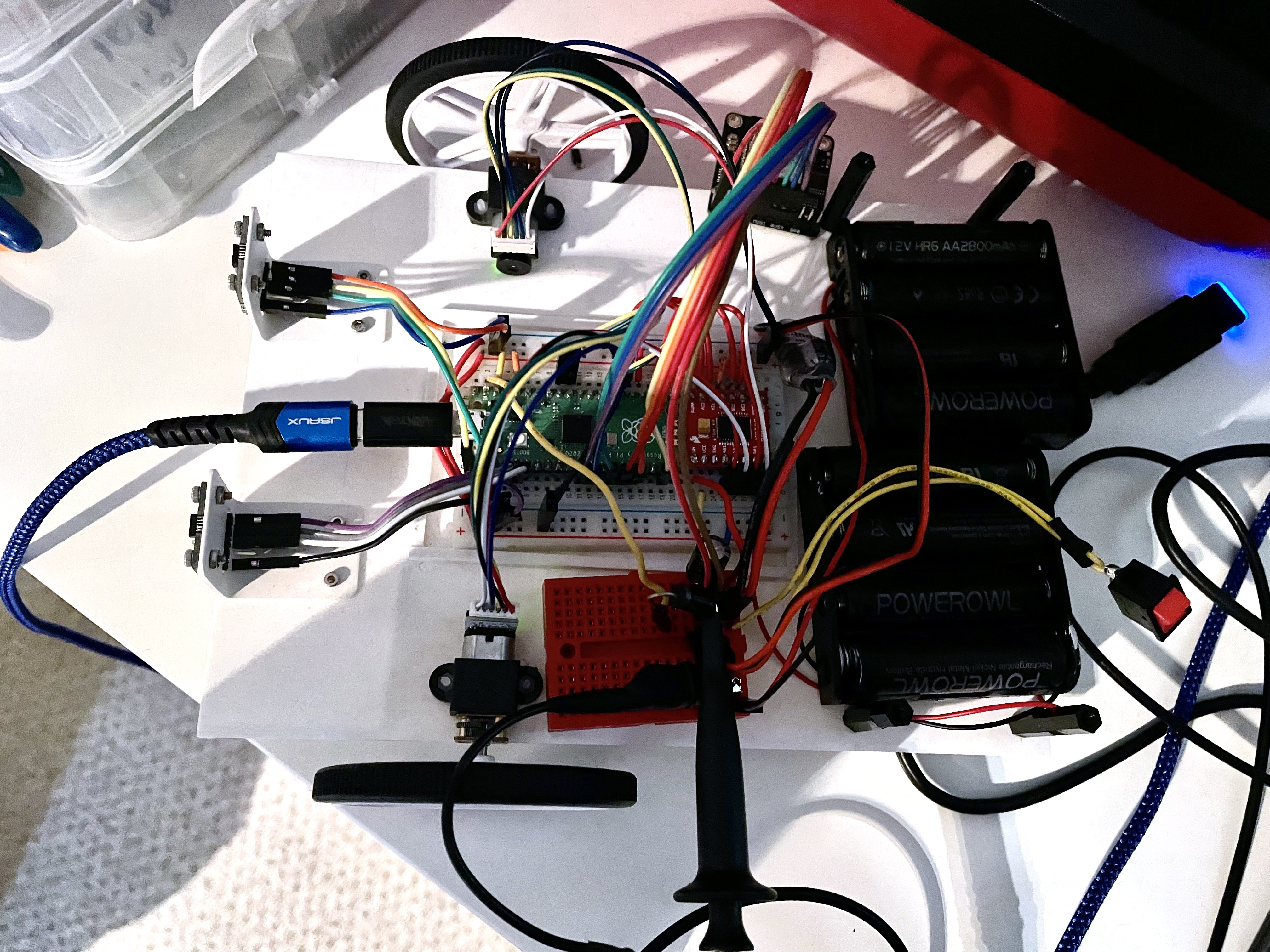
So the answer, shown above, was to move to 8xAA batteries. I started that out with 2x4 boxes as that is what I had in stock. This would mean some rework. But I then looked at options online to buy a proper 8xAA battery box. This required reworking CAD diagrams, purchase lists and assembly instructions throughout the book - for the want of two more batteries.
So this was good - I made progress. I had a nice stable power supply, even during Wifi startup.
The robot was now able to communicate with the ESp32 Wifi (airlift) solution.
Starting with the code
I was now able to start sending packets. I got some example code running, to get version numbers of the device, scan things and check it was alive.
    spi = busio.SPI(board.GP14, board.GP11, board.GP12)
    esp = adafruit_esp32spi.ESP_SPIcontrol(spi, esp32_cs, esp32_ready, esp32_reset)

    if esp.status == adafruit_esp32spi.WL_IDLE_STATUS:
        print("ESP32 found and in idle mode")
    print("Firmware vers.", esp.firmware_version)
    print("MAC addr:", [hex(i) for i in esp.MAC_address])
This code works so I’m now confident I could communicate with the device. It was time to get more ambitious. I made some examples - one to read a sensor data and update a text box, one to control the robot from mouse click drags or touchpad touches, and one to graph sensor data.
These worked, to a point. I use d3.js as a browser component, so I have a way to graph, with graphical interface available too. The basic pattern is to send up a static html page as the index, referencing a d3.js from a CDN.
That d3.js then connects back to endpoints in the robot code to either request data or do things. Because these will be book examples, I’ve steered clear of websockets (there’s also limited circuitpython support for this), or anything requiring client installations other than a browser. The other neat thing is that you’ve now got a phone app.
I do know that polling or repeatedly sending requests has a lot of overhead, and did also consider streaming over http (leaving the socket open, and sending more body/post), again, this is not something that the CircuitPython WSGIApp interface currently supported (or at least I’d not found it). So accepting the overhead to keep it simple I went with tis.
However, all of these examples eventually died. What seemed to happen is one of two things:
- I disconnected/refreshed the browse - the initial examples just died - no retry.
- It lost contact with the ESP32, back to SPI timeouts.
This was going to need some debugging. I won’t dive deep into that in this quite long post, but that I knew that batteries for this debugging were no going to cut it.
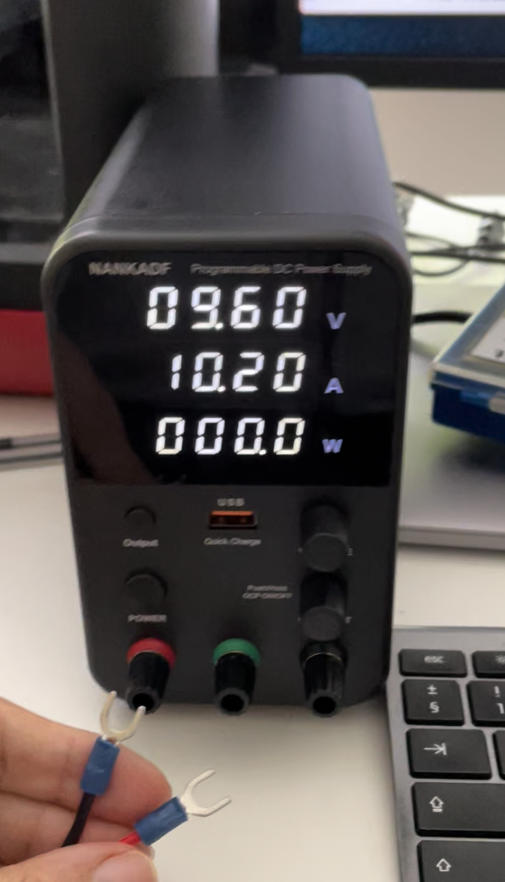
This led me down the route of finally buying a desk/bench power supply. It’s surprising how many years I’ve got by using old plugpacks, batteries and USB power - it was finally time to improve my game.
I made a short video on this power supply WPS3010H Bench Power Supply Review and Unboxing.
Conclusion
I’m not done with this yet. There are still bugs. I will follow up with information about the firmware updates, changes I made to the CircuitPython libraries, and work on potentially investigating the Nina FW itself.
Robotics at Home with Raspberry Pi Pico
This post was based on research I did for the book Robotics at Home with Raspberry Pi Pico which is available now.