Our Pi Wars 2024 robot, Big Ole Yellow, will compete in challenges that require different attachments. So far, the ones we have in mind are:
- The nerf gun for Zombie Apocalypse
- A grab and lift for the Eco Disaster challenge
We’ve been working on an attachment plate, which may become an orionrobots universal attachment plate for our other robots. See the post Dialling in my 3d Printer where Danny was tuning the 3D printer specifically to get better prints on this part.
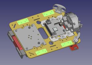
Last week, the team were fixing up the CAD models for the robot in preparation for fixing this plate somewhere on the robot. See the post Progress update for PiWars 2024 for more details on the other parts of the robot. There were holes in CAD that were out of alignment with the real chassis, causing some parts not to fit.
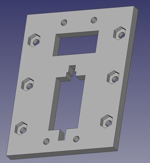
The Attachment plate concept
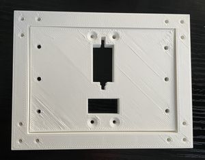
The plate concept is there’s a wiring port, and SG90 servo mount, and a set of holes for bolting things onto. The plate is designed in two parts, a lower mount, and a cover plate. There are recessed holes for dropping nuts in, and the cover plate drops over the nuts, keeping those captive.
That means that we can easily bolt things onto the plate, although there’s still some trickiness in threading cables through to their connections below.
The plate will need to be rigidly mounted on the robot, a little forward. It will need to be mounted on struts or a shell, with clearance below for the Raspberry Pi, and keep it easy to access the GPIO pins underneath.
The base we are attaching to
We are attaching to the aluminium yellow chassis of Big Ole Yellow, using the highlighted holes.
The highlighted holes on the chassis make up 4 holes for each corner, which should let us build a rigid frame to mount the plate on.
Design brief
We then made a design brief for the robot shell and attachment mounting system, based on our constraints:
- We have 4 places on the shell to anchor our top hull
- We want the universal attachment connector to be on the top, a little towards the front.
- Make it not too hard to maintain.
- make it 3D printable for now. Gotta be printable in parts, my printer is only small.
- Keep it simple time is limited.
We had also agreed previously that we’ll try to use M2.5 holes for the parts we design. We’ll have to use other sizes for existing parts, but trying to stick to one size throughout should make things simpler.
The team agreed this all made sense.
Hull design ideas
We had a test version of the plate, but the team were looking at how to mount it. We started by looking at some outline structural ideas in Inkscape. These were to help us figure out how to mount the plate, and what the shell would look like. These were high level designs, with a simple block showing where the holes would be.
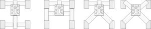
There are few ideas here for us to consider, but all are keeping the plate forward, and with the cable port in front of the servo motor mounts.
For any of these mounting options, we could bolt struts into the chassis, with the other sides bolted to four corner points of the mounting plate. Danny made some quick post-it sketches:
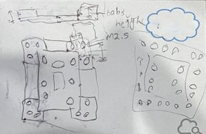
The idea here was that the bolts would be raised in the corners around where the cover plate would sit. This means the cover plate would self align into the recess, and with a little more recess, could help self align attachments too. The corners then just have 3 simple bolt holes in each side. He managed to explain it to the team, even with those scribbles.
Making the plate wider
Danny was detaching the nerf launcher turret from the Bangers and Bash chassis, so Emma could investigate it. Detaching this is a little frustrating due to where the servo sits underneath it. It was this point that Phoebe suggested we should make our plate wider so the attachment mounting bolts are further apart, and not so likely to be under the working parts of an attachment. This is a great idea.
We’ve been using the FreeCAD spreadsheet concept to hold all the dimensions for our design, so it was a great moment to take the earlier attachment design, change one number in a spreadsheet, and see the 3D view in FreeCAD show this change. Labelling everything and linking to the spreadsheet took time earlier in the process, but made this update effortless.
Adding the bolts around the outside
We did some measuring, and for the outer bolts, put a section into the spreadsheet with the thickness of the corner mounting boundary, how deep the recess would be.
We then sketched this into sketches, and padded it around the original base plate. So the cover plate would fit into the recess without sticking, we then cut a section matching the 3D printer tolerances (0.4mm) away.
This is in a different FreeCAD file from the large “everything” robot project. However, Danny added in the reference holes, so the rigid frame can be put in the right place.
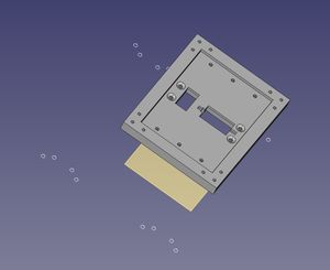
The design above shows the plate floating above the reference holes. The cover plate is in place, with the countersunk inner holes to mount the cover plate, and the 6 outer recess holes for adding an attachment, and the corner mounting holes to attach it to the robot.
Printing it
We started the print, and although the rest of the team had to go, Danny stuck with the 3D printer to get the parts printed.
Based on the cooling tower and time dialling in the printer, the intent was to print the first few layers at 220° C for bed adhesion, then after layer 3 print at 195° C to reduce stringing.
The first attempt at printing it went wrong, Danny forgot to tick the option to use the temperature list, so it attempted print the whole thing at 195° C. Danny found out when he heard an unexpected “clonk” from the printer, as the part had slid off the bed and was moving around with the print head.
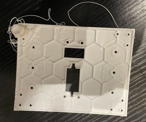
Once it was cleared, and the nozzle cleaned, Danny remade the print with the right temperature settings. The print was successful, although the corners still lifted slightly.
Danny next went to print the cover plate. The print went well, but on inspection, the countersinks had moved from the 4 inner holes to some of the 6 outer holes. This was due to a change to the servo section, which changed the topology of the part. This is a common problem with FreeCAD. Danny fixed this in FreeCAD and printed another one.
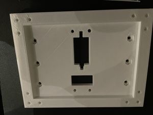
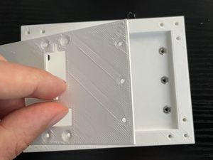
Assembling the mounting plate
This was a few hours of printing, but with the two parts, Danny started assembling the captive nuts into the part:
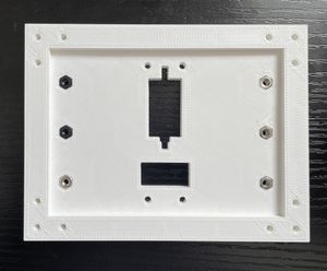
This was a really satisfying moment, using a long screw to slot the nuts into place. Some are metal and some are nylon, which will need replacing with metal ones when Danny finds the pot of 2.5mm metal nuts in the Orionrobots lab.
Danny was then able to place the cover plate over the mounting plate, which lined up nicely due to the self-aligning recess:
This was nearly fully assembled. However, Danny did not have any remaining M2.5 countersunk bolts to complete it.
Danny ordered M2/M2.5/M3 countersunk bolts with nuts (paid link) via Amazon.
Next steps
We are ready to design the side struts to attach this to the robot. We then need to make the adapting plate for the turret that works with the 6 bolts for a quick mount/unmount. The team next meet on Sunday.
Learning CAD design
If you’d like to get started in FreeCAD, there are a few good starting points:
- FreeCAD for Makers From HackSpace Magazine - this book has a few FreeCAD projects to get started with.
- My book Robotics at Home With Raspberry Pi Pico has a chapter on FreeCAD, integrating it into the wider project of building a robot, with using a FreeCAD design to cut a part with hand tools.