I recently have had a reader having trouble with the electronics in Robotics at Home with Raspberry Pi Pico. I’ve been assisting them, and thought I’d share my tips on making electronic systems work. These are some far-from-complete notes on what to look for and try.
Initial issues
Let’s assume you’ve wired a circuit, but it is not behaving. Observations are important here.
- Safety First: If you notice any heat or smoke, disconnect all power sources immediately and do not reconnect them until you understand the issue.
- Observe any unexpected behavior in outputs or code execution.
- Note any occurrences or lack thereof when attempting to run code or establish connections.
Understanding your circuit
Having a clear understanding of your circuit is crucial. Here’s what you’ll need:
- Description of circuit parts and their functions.
- Schematic diagrams or sketches illustrating connections
- Circuit layout diagrams or sketches (e.g., PCB diagrams, board layouts, or breadboard diagrams).
- Data sheets for components.
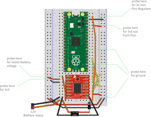
Familiarize yourself with different power lines, including grounds and various voltage levels. In the case of this reader, there were 4 power levels:
- GND or ground.
- 12v motor power, unregulated from batteries, for motors.
- 5v regulated power from the batteries, which only went to a VSYS on a Raspberry Pi Pico.
- 3v3 regulated power from the Raspberry Pi Pico 3v3 out pin.
It is critical to know what power connections in the layout are which. A visual inspection should show you where there are exposed terminals.
Terminology: rails
“Rails” refer to power distribution networks in a circuit, which can be physical (e.g., breadboard rails) or logical connections.
The breadboard rails are the long lines marked red and blue/or black on the breadboard.
The next image shows breadboard layout:
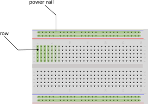
The image has a breadboard, with some rows highlighted in green. Top and bottom are physical power rails, with their green highlights showing which pins are interconnected.
Terminology: regulator
A “regulator” typically denotes a voltage regulator, ensuring a constant voltage output from a variable input.
This is loosely the same as a UBEC (universal battery eliminator circuit), buck converter, DC-DC converter or step-down converter.
Loose connections
You can now check for loose wires or connections, as in anything visibly not plugged in and hanging out. You only want to reconnect things where the diagrams suggest you do.
Polarity issues
These cannot be diagnosed with the multimeter, but if you have components connected, or external board connections, be very sure that the voltage and ground pins are the correct way around, and that the voltage pin is connected to the appropriate voltage level.
In the case of sensors, many will output a voltage high based on their VCC input voltage, so if you are using a 3v3 logic device like a Raspberry Pi, Raspberry Pi Pico, ESP32, they should have this 3v3 connection. Do consult the devices data sheet for this.
Looking for shorts
You will now want your multimeter. A multimeter has a continuity mode, which usually has a musical note symbol to show it will beep.
You can check you are in the right mode by pushing the metal ends of the multimeter probes together, and you should hear it beep.
Find the input power points and check pairs of these. There should be no continuity between any power lines of different power rails.
Choose some suitable pins that should be connected, and use those as test points.
Short circuits between GND and any voltage, or between higher and lower voltage rails can cause major problems, heat, melting wires, blown components, even smoke and fire.
You need to try the pairs across all the different power levels: GND and 5v, GND and 3v, GND and motor power (12v?), 3v and 5v, 5v and 12v, 3v and 12v. None of them should have continuity between them.
If you find any, you will need to check first all the wiring, and then for damaged components, as some fail in a way that creates a short between different pins.
If there has been heat or smoke, a short like this is the most likely condition. For these cases, check all lines for shorts before attempting to reconnect the circuit.
It can mean:
- A wire connected to the wrong rail or pin.
- A component connected in an off-by-one configuration.
- A component connected the wrong way around.
- A failed component - you may need to disconnect wires to diagnose this, but if a VM and VCC are showing a short, that can mean the motor controller is damaged, which could be symptom of the original problem, or the cause.
- Accidental contact between wires - ensure that there’s not much bared wire (with insulation removed) past a connection, ensure that any small components like resistors, capacitors, diodes etc have their legs touching.
- Accidental contact with conductive surfaces - depending on where your board is being tested, you may have metal surfaces under the board. Beware - as pins from under the board could make contact with this, and then use it conduct between them. A layer of insulating tape can be used, or stand offs to ensure there’s a gap. If it’s a free-standing board, rubber feet should hold it clear from the surface under it.
When you are sure that there are no issues like this, you can reconnect the board, and see if it behaves. If component damage has already occurred however, it may still not work without the component being replaced.
Connection issues
If the circuit has no shorts, no heat or smoke, then the next problem can be that a component is not connected to power.
At this point, you must now check that anything expected to be connected to 3v is. Pick two places that should be 3v, and ensure they do have continuity, and if not, check all connections between them.
Repeat this for every other power line and ground.
You would then go into performing this for the data lines. Expect to make many continuity checks.
Again, verify the wires are in the right holes. Being off by 1 or 2 is very common.
Poor connectors or solder joints are an all-too-common problem too, so check crimps and solder joints. Broken or kinked wires can also cause this.
If there has been any heat before, some components here might not work properly again after that event, and will need replacement.
Are we done?
Not yet, there’s definitely many more ways to diagnose a circuit and it’s malfunctions. However, I hope this guide gets people started on what to look for.