This week I’ve been reading Lukas Kaul’s robotics book “Practical Arduino Robotics”, and trying the experiments within. Although I am experience with PID control. encoders and the Arduino, it is always useful to read and try the work of other robot builders and see what I learn from it.
Today’s experiment is trying the arduino pid control demonstration in Practical Arduino Robotics. I took a few liberties, using a Nano instead of an Uni, using a tt motor encoder assembly, using the dir pins for pwm (2 pins per motor, but uses more pwm outputs).
The Setup
The book called for an Arduino Uno, however I had a Nano to hand. I also had a half+ 400 tie point breadboard, some jumper wires, an L298n motor driver board.
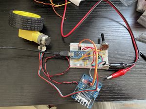
About the motor
For the motor, I used a TT Motor with encoders from The Pi Hut. While I often use the n20 type, I have a few of these TT ones around too and should make use of them - this one is nice as it has a metal output shaft - not sure if it is a metal gearbox inside. The encoder is a magnetic hall-effect quadrature encoder. The encoder allows you to detect the relative change in position of the motor.
Power input
For power, I used the USB from my computer for logic, also useful for programming and monitoring the Arduino. For motor power I used my bench power supply, set to 6v with 1.5amp limit (it never needed that).
Motor driving pins
I wired it using 2 PWM pins to control speed and direction, so slightly different from Lukas’ code, using 2 pins per motor instead fo 3 - I usually do this with L298n control. This mean I had to adapt his code a little to fit - but I wrapped in the same void setMotorPWM(int motor_pwm).
Experiment Idea
The Arduino Nano is detecting pulses from the encoder (using interrupts), updating a relative position then using a PID control loop to match the potentiometer input position. This is from the Feedback Control section of Chapter 5 in the Practical Arduino Robotics book.
Code changes
I used mostly the code from the book, but because I was commenting in and out tests while ironing out any silly wiring mistakes (I made a few), my loop function looks a bit different:
void loop() {
  // test_motor();
  // test_encoder();
  test_controller_task();
  print_controller_task();
  target_position = analogRead(A0);
}
Problems I ran into
Connections - I had gone off by one where the encoder inputs were wired into the breadboard. The result was only one encoder input made it.
Motor - I reversed the pin order in the code, as the motor initially went entirely backwards with the PID control before I turned off power.
Flashing the Nano - I’ve had these in my cupboards a long time, and when trying to upload the code on it I got errors. However, I vaguely remembered that I had to use the old bootloader option in the Arduino IDE. This worked.
Things I learned from his style
- Lukas declares the units of his error input to the PID controller. It makes it easier to reason about the controller. This is a good technique which I’ll use in future.
- I like the way he has explained cooperative multitasking.
Things I learned from the experiment
This was a good refresher on PID control and looking at how he’d implemented it. There was a small gap between the target state and actual, however, increasing the integral gain always lead to oscillation. I found increasing the P term (and D term to compensate) worked better to reduce these - so it effectively stayed a PD controller.