I’ve recently been specifying changes to a fleet of robots used in my local Coder Dojo. The modified robots would be based on a Raspberry Pi Pico W, and a bunch of sensors.
I started with specifying a fully loaded robot, bristling with sensors, with the plan to work backwards to a simpler robot once I found some activities that would lend themselves well to the coder dojo format.
The fully loaded robot would have the following sensors:
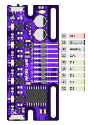
- A Cytron maker line sensor (see How to add line following to a robot with Raspberry Pi Pico and Python/)
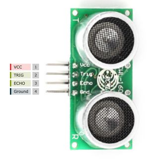
- Two RWCL-1601 Ultrasonic distance sensors
- Two optical motor encoders
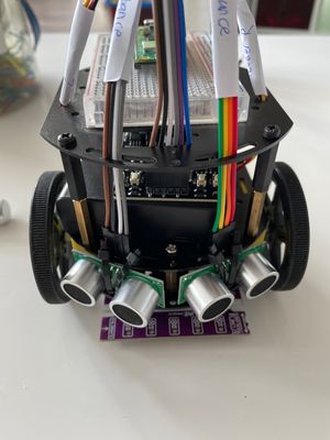
I also needed connections for power, and the motors via a Cytron motor MDD3A driver. The robot was waiting for me to wire it up:
This set of sensors meant there were quite a few connections to the Raspberry Pi Pico, which I needed to sketch out both for myself, for other mentors to help fix a robot, or for the Ninjas (students) at the Dojo to repair if needed. That means they will need to be on a quick reference card.
Demonstration Card
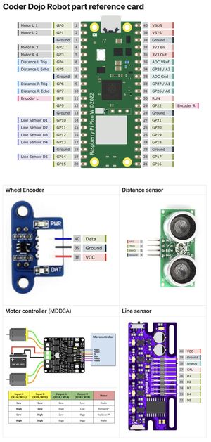
Here’s the card I came up with:
How I made the card
Datasheets
At the start of any project, I grab the datasheets or web links for each of the devices. I tend to put PDF’s into an Obsidian vault and link to them from a markdown note. That way i can find them all from the project. I may also take screenshots of the pinout parts of the sheet and put that into the note.
If I’ve already got those datasheets, it is somewhat easier as I just search for them while linking in Obsidian.
The datasheets are also useful for finding out what the pinout is for the device along with other parameters
Pinout.xyz
The marvellous Gadgetoid, a long time contributor to the Raspberry Pi community and Sheffield pirate has made web pinouts for the Raspberry Pi, and the Raspberry Pi Pico. This website is a great resource for finding out what pins are available on the Raspberry Pi Pico, and what they are used for.
He has also made the code for the PicoW website open source. I was able to use this to make the pinouts of the parts in a matching style
This code is html, css stylesheets and some images. I checked this code out from Github, and fired up a text editor.
Making the pinout for the waveshare encoder
The first thing I did was find an illustration of the encoder device. The one in it’s datasheet worked fine, trimmed a bit using a simple preview tool. I put this in the root of the project as waveshare-encoder.png.
I then made a copy of the file picow.html and called it waveshare-encoder.html. There are a few steps to changing this file:
-
Change the image to waveshare-encoder.png:
<div class="pico"><img width="196" height="294" style="padding-top: 15px;" alt="Waveshare optical encoder standing on its side." src="waveshare-encoder.png" /></div> -
Adjust the image width and height to match the image size - or a multiple of. Keep the aspect ratio the same.
-
Since the image of this has pins facing right, delete the whole left hand pins section. This is the section that starts with:
    <table aria-label="Lefthand pins" class="labels left" aria-rowcount="20" aria-colcount="5" cellpadding="0" cellspacing="5">
        <thead>
and ends with:
</tbody> </table> -
Remove all but three of the pins in the right-hand pins section.
-
We can adapt these to match the pinout of the device:
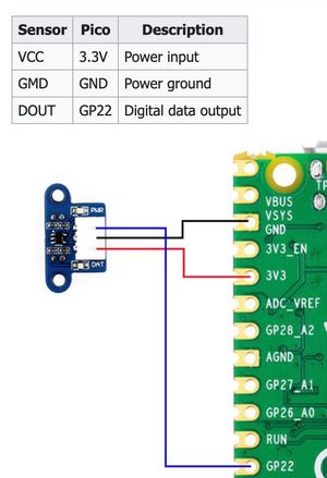
            <tr aria-label="First pin."       ><th>1</th> <td class="gpio" title="Digital data output">Data</td></tr>
            <tr aria-label="Second pin."      ><th>2</th> <td class="ground" title="Ground">Ground</td></tr>
            <tr aria-label="Third pin."       ><th>3</th> <td class="power" title="Voltage">VCC</td></tr>
Note this has pin classes, which colour them differently. I’ve used the classes gpio, ground and power. These are defined in the css file. I’ve also added a title to each pin, which will show up when you hover over the pin.
-
There will be too many columns in the pin table, for optional parts of the PIcoW pinout. We can reduce the table heading to the two columns:
        <thead>
            <th>Pin</th><th>Name</th>
        </thead>
These aren’t needed for making the card I did, but these optional steps make the page usable on the web.
- Change the title to “Waveshare Encoder” - optional step. Everywhere it says “Raspberry Pi Pico W” change it to “Waveshare Encoder”.
- We also don’t need the navigation bars at the top. You can optionally remove this. It’s the section that starts with
<nav class="nojs" id="nav">and ends with</nav>.
You can then load this page into your browser. You can see the complete code at https://github.com/dannystaple/sensor.pinouts.xyz.
Making the pinout for the other sensors
I repeated this process for the other sensors and boards. This led me to get screenshots of each. Note that sometimes I remove the right pins instead of the left pins, depending on the orientation of the device image.
I didn’t create one for the motor controller, and used the data sheet diagram for now, but I may come back to this.
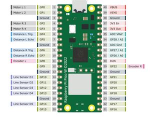
Altering the Pico Pinout
I then took a copy of the picow.html file, and called it picow-coder-dojo-wiring.html. This I would use to add specific pinouts for the dojo robot. I wanted to have colours specific for the distance sensor, line sensor and encoder inputs. So I created a dojo.css file with a new set of classes for these, derived from the way classes were in the pinout.css file:
.distance    {background-color: #268bd233;border-color: #268bd2;}
.encoder    {background-color: #d3368233;border-color: #d33682;}
.line   {background-color: #6c71c433;border-color: #6c71c4;}

.labels tr:hover .distance    {background-color: #3ba6f166;}
.labels tr:hover .encoder    {background-color: #f34f9f66;}
.labels tr:hover .line   {background-color: #8d91e666;}
Handy tip: I used the colour picker built into VSCode for these.
In the HTML file, I again removed the nojs nav, as this robot does not use I2C, SPI or UART functionality. This made the file simpler. I also reduced the table headings to just the following columns:
<th>Pin</th><th>Name</th><th>Other</th>The Other column is for how they will be used in the Dojo robot. I suggest keeping the pins the same for the fleet, since it makes the sheets easier for the Ninja;s and mentors to use.
For the pins, I removed any pin designations other than the basic GPIO/Power, then added the functionality I’d assigned for the Dojo. For example, the motor pins on the left use the existing PWM class:
            <tr aria-label="First pin."       ><th>1</th> <td class="gpio">GP0</td><td class="pwm">Motor L 1</td></tr>
            <tr aria-label="Second pin."      ><th>2</th> <td class="gpio">GP1</td><td class="pwm">Motor L 2</td></tr>
            <tr aria-label="Third pin."       ><th>3</th> <td class="ground" title="Ground">Ground</td></tr>
            <tr aria-label="Forth pin."       ><th>4</th> <td class="gpio">GP2</td><td class="pwm">Motor R 3</td></tr>
            <tr aria-label="Fifth pin."       ><th>5</th> <td class="gpio">GP3</td><td class="pwm">Motor R 4</td></tr>
The sensor pins then use my new CSS classes:
            <tr aria-label="Sixth pin."       ><th>6</th> <td class="gpio">GP4</td><td class="distance">Distance L Trig</td></tr>
            <tr aria-label="Seventh pin."     ><th>7</th> <td class="gpio">GP5</td><td class="distance">Distance L Echo</td></tr>
            <tr aria-label="Eighth pin."      ><th>8</th> <td class="ground" title="Ground">Ground</td></tr>
            <tr aria-label="Ninth pin."       ><th>9</th> <td class="gpio">GP6</td><td class="distance">Distance R Trig</td></tr>
            <tr aria-label="Tenth pin."       ><th>10</th><td class="gpio">GP7</td><td class="distance">Distance R Echo</td></tr>
I continued it for the whole device, and took a screenshot of the resulting output:
Compositing them
I now had these screenshots as PNG files in a Coder Dojo Robots folder in my Obsidian vault. I created a Coder Dojo Robot part reference card note in the same folder.
At the top of this file, I dragged the Raspberry Pi Pico-W Coder Dojo layout image. Below this, I used markdown to make a table with the other images in it:
Wheel Encoder | Distance sensor
------------- | ---------------
![[Waveshare Encoder.png]] | ![[RCWL Pinout.png]]
**Motor controller** (MDD3A) | **Line sensor**
![[MDD3A Pinout.png]] | ![[Cytron Maker Line Sensor.png]]
This gave me a table with the images in it, resulting in the card at the top of this post.
Conclusion
This was a neat way to make a reference card for the project. I used this reference card to build and wire up the robot, and I was able to share it with a mentor who will be collaborating with me on making some worksheets for these robots, and getting familiar with assembling one himself. Now I’ve learned this technique, I’ll be refining it and using it for further robot projects - guides or worksheets for students, for my own reference, and for online content around them.
After wiring this robot, and some test code, I got it to do the line following in my previous post How to add line following to a robot with Raspberry Pi Pico and Python/. I’ll be writing up the worksheets for this soon.
Gadgetoid has made a neat little tool here, which I hope to use again.
Making your own robot projects
If you are new to robotics and yet to build a robot like these starting from basics like a Chassis and motors, or experienced but want to touch on advanced techniques like Monte Carlo Localisation and the PID algorithm, then Robotics At Home With Raspberry Pi Pico is for you. It’s a book I’ve written showing how starting from little knowledge of the Raspberry pi Pico ecosystem, you can build an autonomous robot, learn CAD techniques, program it, extend it with sensors and interesting behaviours.