While discussing my book with one of my readers, an error in the circuit diagrams, replicated in a number of them, has been spotted. I am writing this article as a correction to those errors.
Chapter 9
These start with wiring in chapter 9, adding the LED strip in, where the Line sensor was already wired. The chapter 8 photos are correct, and adding only the additional wires for chapter 9 would lead to things being fine. However, if a chapter was to skip the chapter 8 straight to chapter 9, the wiring there would be incorrect.
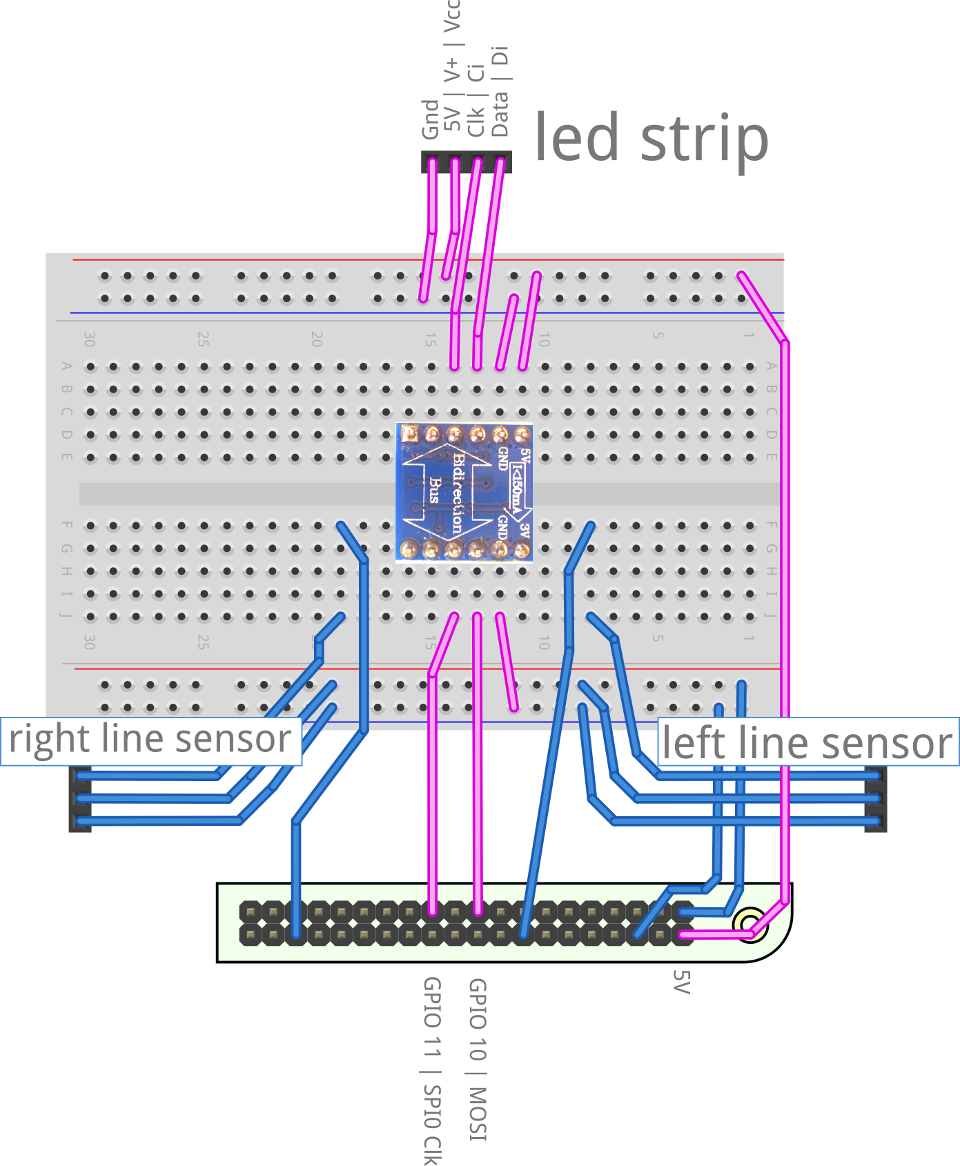
The difference is subtle, but in the bottom right of the breadboard, the power connectors have been reversed. This reflects what is shown in chapter 8 now.
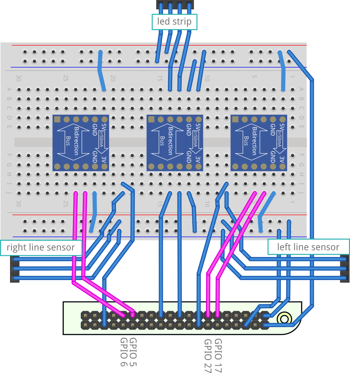
Chapter 11
In this chapter, we add a pair of distance sensors. If you have The diagrams here all have the same problem. Here is the first of the diagrams shown with the same reversal.
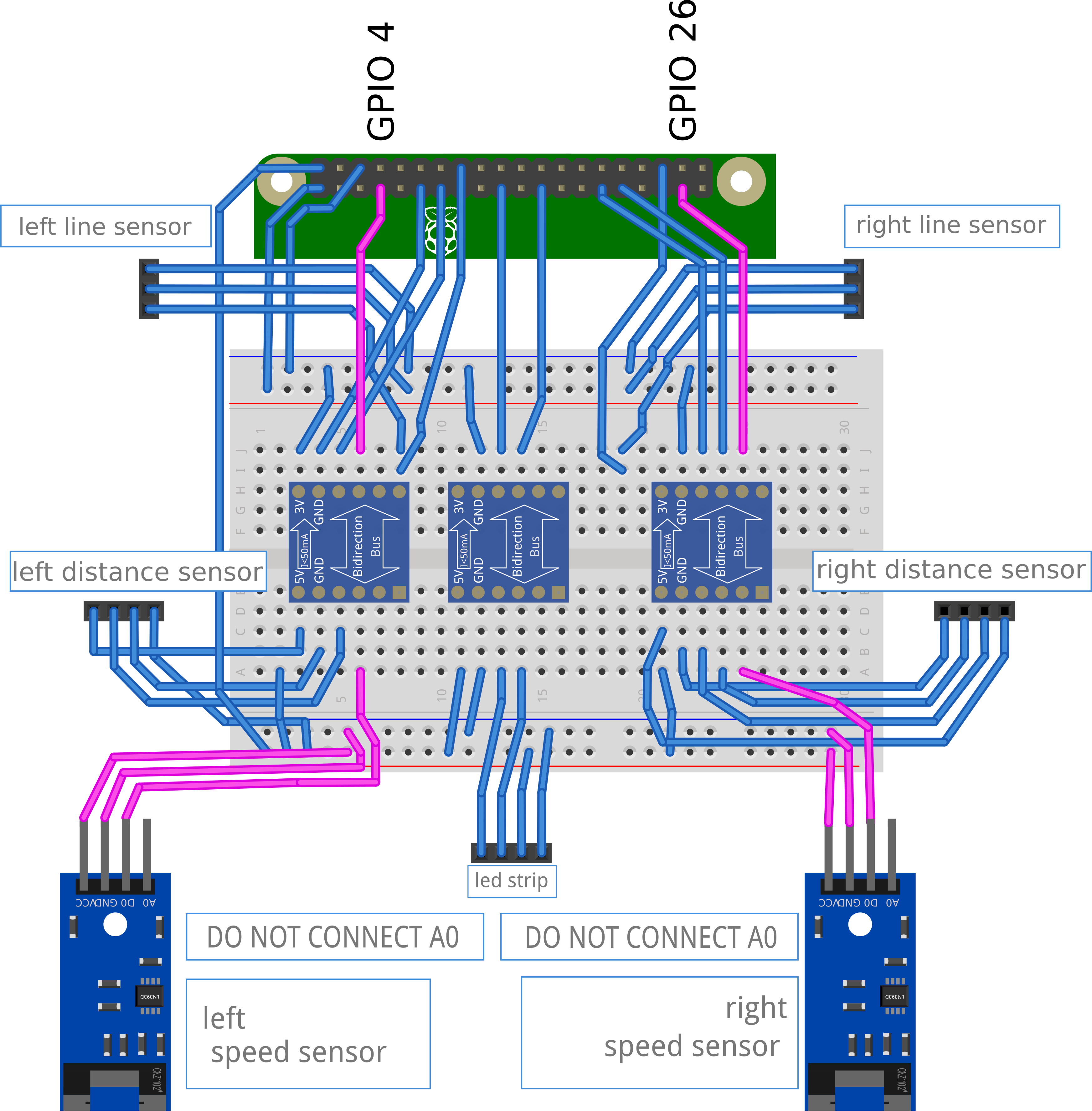
Chapter 12
In chapter 12 of the book, encoder sensors, detecting motor movements, the reversal was only part of the problem. There was also a transposing of the level shifters in the diagram shown here.