This week, I’ve started building an esp8266 based hexapod, which I’ve nicknamed “SpiderBot”.
I’ve been wanting to build a hexapod for a while, and I’ve been building a lot with esp8266. I’ve also been wanting to do something with the PCA9685 servo controller for a while. So I’ve decided to combine all three.
Parts I used
- A NodeMCU esp8266 board
- An Adafruit PCA9685 16 servo controller board
- An 18 servo hexapod laser cut kit from Hobby Components.
- 18 SG90 plastic gear servo motors
- A 5V 10A power supply
- The NodeMCU base board - from icstation.com.
- A HC-SR04 ultrasonic distance sensor.
About the parts
The Hexapod Chassis Kit
This was a lasercut kit I bought from Hobby Components. This laser cut kit is a little flimsy, but came with screws to connect it together and relied on the servo horns to hold the legs together.
The model number: HCROBO0028. This has images showing it assembled, but no instructions.
I also found that laser printed legs have some traction issues on different surfaces.
It requires 18 servo motors to move the legs.
SG90 Servo Motors
These are small, plastic gear servo motors. They aren’t particularly high quality and while small and cheap, have a habit of stripping gears. They can pull a lot of current while running, especially when there are 18 of them.
The PCA9685
The PCA9685 is an i2c based servo motor driver, capable of driving 16 servo motors (or other loads).
Using PWM it can output different pulse chains at different frequencies or duty cycles.
I2C uses only a few wires to connect to the esp8266, which only needs to send a few control commands and let the PCA chip handle the PWM control. This uses only two pins on the esp8266, and can be shared with other devices as well as freeing up other IO pins to be used for sensors.
It can control 16 servo motors, so I needed to use 2 additional pins on the NodeMCU.
The NodeMCU Base
This board was provided by ICStation. It is a breakout board for the NodeMCU esp8266 board, and provides a number of useful features:
- Onboard power converting from an input of 6-24Vdc to 5v/1a and 3.3v needed by the NodeMCU.
- Breakout headers for IO pins making wiring much easier
- Power On LED
It may be overkill for this project, but it is a useful board to have around.
It did have some useful silk screen printing, but didn’t show the polarity for the power input, which I had to work out with my multimeter.
The NodeMCU
This is the trusty esp8266 that we’ve seen before. In this case I am running MicroPython on it. The aim will be to get the robot walking, add wifi to drive it, then add sensors and make it autonomous.
The HC-SR04
This is an Ultrasonic distance sensor. Until there’s code to connect it, all it presently does is identify which end of the robot is the front, and give it a “cute” face.
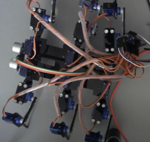
The Build
I started by peeling the backing off all the laser cut parts.
I then went into making a complete leg assembly with 3 servo motors, and then attaching that to the body, using the HobbyTronics images as a guide. The intention is to get good rigid connections for each joint so the robot can walk. What i should have done was to set each servo at it’s middle 90 degree position before tightening screws, which would have made later steps easier.
I then repeated this 5 more times. It was during this build that I discovered the wire wrap which came with the part for keeping the large number of wires under control.
At this point I had a chassis, with legs but no electronics to drive them.
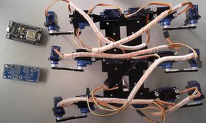
The Electronics
This wiring was mostly made using Dupont 2.54mm wires - first the servo board to the NodeMCu using D1 and D2 as I2c pins. I used the Adafruit PCA9685 Tutorial for connecting the PCA9685 to the NodeMCU.
I connected the grounds together and logic voltage, and then connected the servo motors onto the servo board.
I crimped connectors for the remaining two servo motors, bringing ground, voltage and a signal pin out for each of the two motors, and connected them to D3 and D4
I then connected the ultrasonic sensor to D5 and D6.
I powered this with wired power - connecting a large 6v power supply to the voltage in supply, and an extra USB 5v into the nodeMCU as I saw some power drops while the motors ran.
Initial wiring was without the boards being mounted in the robot, so i could test it out.
The code and first tests
All my code is at https://github.com/orionrobots/esp8266_video_series/tree/spiderbot_smaller_with_web/spiderbot.
For this, I used the Adafruit MicroPython PCA9865 library from https://github.com/adafruit/micropython-adafruit-pca9685 to interface to the device, along with another servo library. In the video above, I take a good look at these libraries.
The initial part was to connect to each device and test the servo motors, along with a servo wrapper for the additional 2 motors.
I made MicroPython classes to wrap each of those servos so they had the same interface. First the PCA9685:
class Servo9686:
    def __init__(self, adafruit_servo, index):
        self._servo = adafruit_servo
        self._index = index
        self.invert = False

    def position(self, angle):
        if self.invert:
            angle = 180 - angle
        self._servo.position(self._index, angle)

    def release(self):
        self._servo.release(self._index)
This is a fairly light wrapper. It takes an Adafruit PCA9685 servo object, and an index, and then provides a position method that takes an angle, and a release method. Note the invert parameter, this allowed me to treat the legs on the left and right side of the robot as mirror images of each other.
The direct pin controlled servos needed a class with the same interface, but different implementation:
class ServoDirect:
    def __init__(self, pin):
        self._servo = DServo(pin)
        self.invert = False

    def position(self, angle):
        if self.invert:
            angle = 180 - angle
        self._servo.write_angle(angle)

    def release(self):
        self._servo.write_us(0)
I set each motor to 90 (do this before assembly), so I could line them up with a screw driver.
I chose this as the neutral position for now:
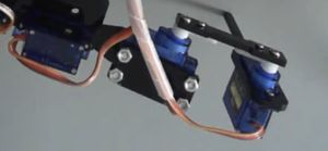
The leg is going straight out from the hip, and the knee is straight. The foot is at a 90 degree angle to the knee.
The next thing I needed to do was arrange the servo motors into a list.
s = servo.Servos(i2c)
servo_list = [Servo9686(s, n) for n in range(16)]
servo_list.append(ServoDirect(Pin(0)))
servo_list.append(ServoDirect(Pin(2)))
Arranging legs
It was at this point I chose one end as the front of the robot, and stuck on the ultrasonic sensor with double sided tape.
I could then reference the list of servo motors as legs. I made a table in the code to help me with this:
From the front:
          00
--0--0--0    0--0--0--
  1  0  2    4  3  5
--0--0--0    0--0--0--
 11 10  9    6  7  8
--0--0--0    0--0--0--
 14 12 13    17 15 16
I also created a class to represent a leg:
class Leg():

    def __init__(self, robot, hip, knee, foot, invert=False):
        """Hip, Knee and Foot are Servo classes.
        Invert will invert angles on hips and knees"""
        self.hip = robot.servo_list[hip]
        self.knee = robot.servo_list[knee]
        self.foot = robot.servo_list[foot]
        if invert:
            self.hip.invert = True
            self.knee.invert = True
            self.foot.invert = True
These legs took a set of servo motors (it doesn’t matter how they are connected), and if the leg is on the left side of the robot, the angles are inverted.
We can use those legs to make our robot.
self.left_side = [
    Leg(self, 2, 0, 1),
    Leg(self, 9, 10, 11),
    Leg(self, 13, 12, 14)
]

self.right_side = [
    Leg(self, 4, 3, 5, invert=True),
    Leg(self, 6, 7, 8, invert=True),
    Leg(self, 17, 15, 16, invert=True)
]
I was then able to enable a MicroPython Web REPL (an esp8266 build feature), which let me test code directly on the robot without having to tether it to a computer.
At this point, I was checking a few positions with the motors and legs, but haven’t yet started to play with walking gaits, and putting the electronics on top.
At this point I had to stop for the day.
Next Steps
Next time, I’ll be looking at walking gaits, and getting the robot to walk. I’ll also be looking at mounting the electronics in the chassis.