Building a Bump Sensor For The Orion Explorer 1 Kits
 The Explorer 1 can be extended fairly simply. Here is how to build a bump sensor that looks a little like insect antenna for the robot. It uses 2 IO pins on the Arduino, and needs 1 power pin. This can be done with parts from the kit, a bit of piano wire, a screwdriver and some pliers!
Materials Needed
From The Explorer 1 Kit
- Your Explorer 1 Robot
- 3 x 3m nuts
- 2 x short 3m screws
- A ribbon of 3 jumper cables
From A Hardware Store
- Around 20-30 cm of thick guitar string or piano wire. The lower G from a guitar seems to do. Must be the metal conductive type.
- 1 x long 3m screw
- 1 x 3m washer
Tools Required
- Small flat head screwdriver
- Small wire stripper
- Small long nosed pliers with cutting area
Method
First peel the strip of 3 cables from the remaining male-female jumpers in the kit. Cut the 3 cables a couple of centimeters from the female end. Strip about 0.5cm from each cable, and twist the copper ends of each.
Now take the thick wire - take care cutting this. Place a kink in the middle of this section using the pliers. The middle kink will go in the middle of the robot.
On the Robot, carefully separate the two sections by unscrewing the bottom posts. I recommend you separate the wiring and replace it using the construction guide later. Gently remove the battery box and place it to one side.
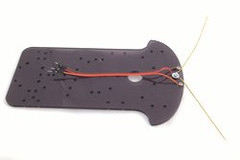
Take a look at the front middle of the robot platform - there is a formation of 5 screws at the very front middle - 2 forward and 3 back. Place the 2 short 3m screws in the top two, and loosely screw on a nut. Place a washer on the long 3m screw, and push this through the middle back hole here. Again - screw a nut on just enough to retain the nut.
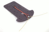
Take the piano wire, and put the kink under the washer. Push the middle copper end from the ribbon between the piano wire and the washer - ensuring the two ends of the piano wire are facing forward, tighten down the screw and nut (you may need to use a small spanner or could use the pliers carefully for this) until both the piano wire and the copper cable is retained under the washer.
For each of the other remaining two copper ends, push each around the left and right short screws and tighten them.
You now need to make bends out from the kinked area using the pliers. The goal is to bend the antenna out so they are very close to the short screws - so a bit of pressure will make contact with it, but so they spring out and away from it. Make the bends as close to the washer holding the antenna as possible.
Note that in the image - the sensor has been assembled on a new clear platform for clarity. You should still have the motor board attached.
Now reassemble the robot - start with the battery box, ensuring that the sensor cables are in front of it, and not caught under it when you stick it back down. When you reassemble the two halves, push the sensor ribbon through the hole above.
Screw the platforms back together. Connect the motors using the guide, and then connect the sensors middle pin to the ‘IOREF’ pin on the Arduino. The left, and right pins can be connected to any remaining digital IO - skipping 0 and 1.
Programming Tips
Source code will follow soon. To program this, set the pins you’ve used to DigitalInput pins. Create or use a loop function, starting with some if-statements - the following logic (this is pseudo code) would do:
if right sensor is true: backup a little turn left else if the left sensor is true: backup a little turn right else: go forward.